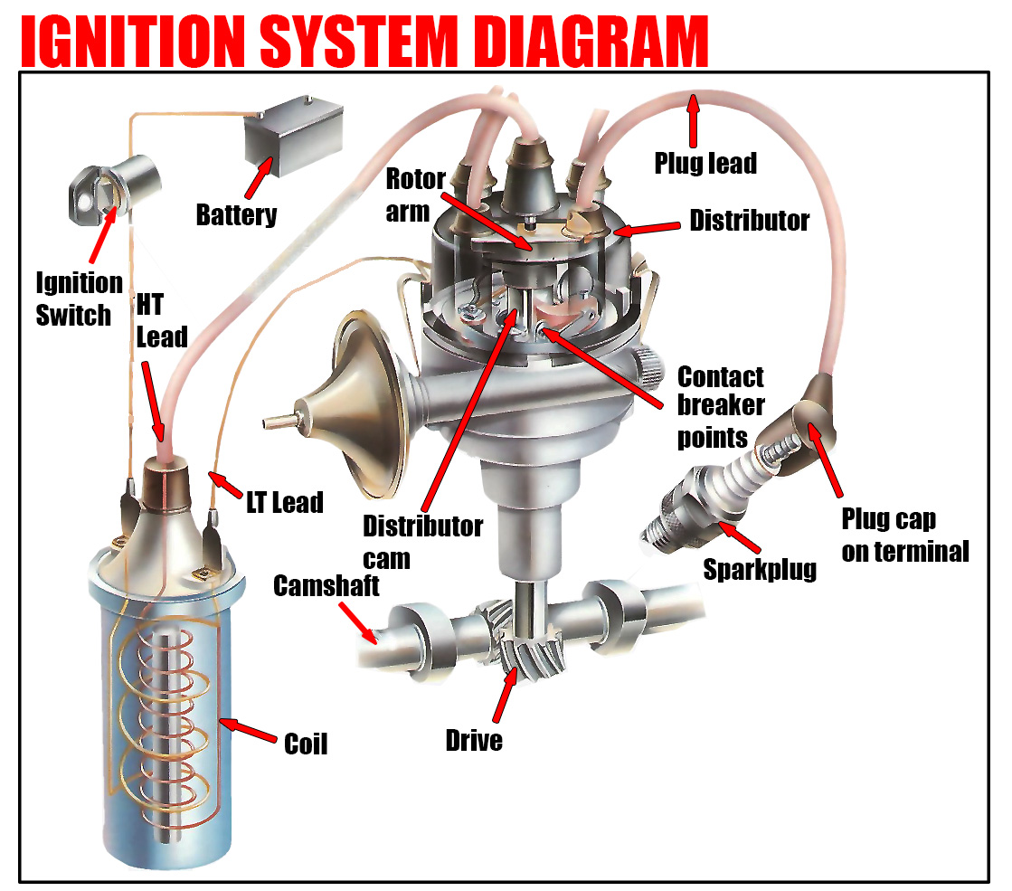
The ignition system’s function is to amplify the car’s 12-volt battery power into a much higher voltage and channel it sequentially to each spark plug, igniting the fuel-air mixture in the engine’s combustion chambers.
Ignition Switch and Battery Role
Usually located on the steering column or dashboard, the ignition switch regulates the current flow between the battery and the ignition system. When the engine is not running, the battery provides electrical power and supplements the generator when it isn’t spinning fast enough to produce 12 volts.

Distributor and Condenser
The distributor routes the high-tension current from the coil through the rotor arm, sequentially sending it to each spark plug. A condenser, mounted on the distributor, prevents sparking across the points when open, which could damage the contact surfaces.
Spark Plug Operation
The high-tension current travels through the center of the spark plug and creates a spark by jumping the gap to the side electrode, igniting the fuel-air mixture in the cylinder. Typically, the distributor is directly driven by the camshaft and rotates at half the engine speed.
Coil Functionality
The coil consists of a metal casing with two sets of insulated wire windings around a soft-iron core. The magnetic field collapse around the primary windings generates high-tension current in the secondary winding, which then flows through the distributor to the spark plugs.