
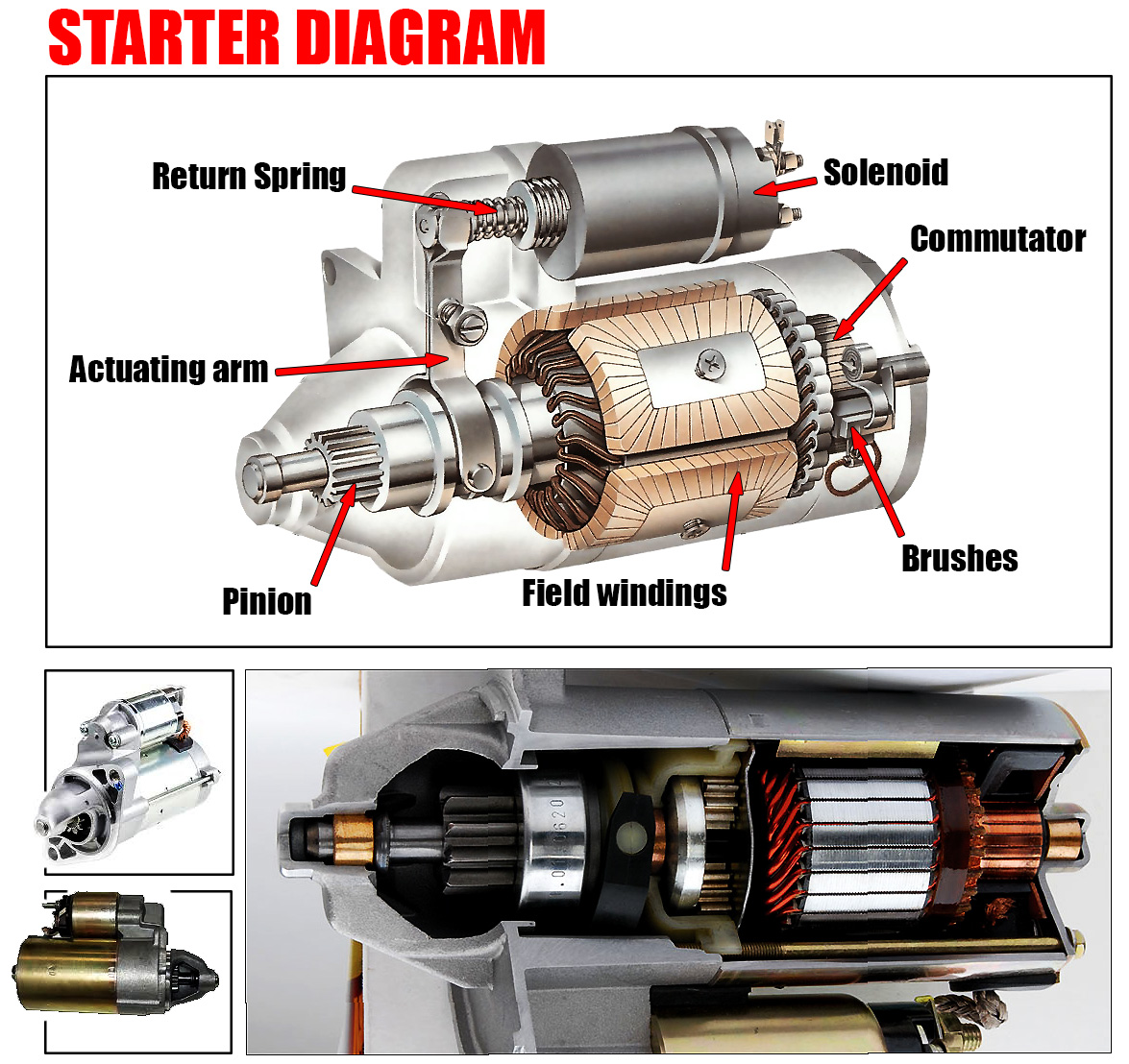
Starter diagram provides an essential visual presentation of the starter system in an engine, detailing how the engine is initially turned over to begin its operation. The starter system initiates the engine’s operation by providing the necessary force to draw in air and fuel, compress it, and kickstart the combustion process. In this article, we’ll break down the key elements of a starter diagram and explain how the components work together to bring an engine to life.
The Role of the Starter Motor
The heart of the starter system is the powerful electric starter motor. This motor is responsible for turning the engine over at a speed sufficient to draw fuel and air into the cylinders and compress the mixture, preparing it for ignition. The starter motor’s shaft carries a small pinion gear, which engages with a larger gear ring mounted around the engine flywheel’s rim. This interaction is what physically turns the engine components, allowing the starting process to begin.

In vehicles with a front-engine layout, the starter motor is typically located low down, near the back of the engine, where it can efficiently engage with the flywheel.
The Need for Heavy Current and Solenoid Activation
Starting an engine requires a significant amount of electrical power, far more than what an ordinary hand-operated switch could handle. The starter motor draws this heavy current through thick wires connected directly to the vehicle’s battery. To manage this high current safely, a robust switch mechanism is required.
This is where the solenoid comes into play. The solenoid is an electromechanical device that uses a small switch to activate an electromagnet. When the ignition key is turned beyond the ‘ignition on’ position, it sends a current to the solenoid, which then activates the electromagnet. This electromagnet, in turn, pulls an iron rod to close two heavy contacts, completing the electrical circuit between the battery and the starter motor. The solenoid ensures that the high current needed to start the engine flows safely and efficiently.
Return Springs
Both the ignition switch and the solenoid system are equipped with return springs. The return spring in the ignition switch ensures that once the key is released, it automatically returns to the ‘ignition on’ position, cutting off the current to the solenoid and stopping the starter motor. This automatic disengagement prevents the starter motor from running longer than necessary, which is important for a couple of reasons.
First, the starter motor consumes a large amount of electricity, which can quickly deplete the battery if left running unnecessarily. Second, if the starter motor remains engaged after the engine has started, the engine’s higher speed could cause significant damage to the starter motor by spinning it too fast.
The Bendix Gear and Engagement Mechanisms
The starter motor includes a device known as the Bendix gear. The Bendix gear is responsible for engaging the starter motor’s pinion gear with the flywheel’s gear ring only while the engine is being turned over by the starter. Once the engine starts and picks up speed, the Bendix gear automatically disengages to prevent any damage to the starter motor.
There are two primary systems used to achieve this disengagement: the inertia system and the pre-engaged system.
Inertia System: In this system, the rotational speed of the starter motor forces the Bendix gear into engagement with the flywheel. Once the engine starts and exceeds the starter motor’s speed, the inertia of the spinning flywheel disengages the Bendix gear.
Pre-Engaged System: In contrast, the pre-engaged system uses the solenoid to both engage the Bendix gear and close the electrical contacts that power the starter motor. This system is more controlled, as the solenoid ensures that the pinion gear is fully engaged before the starter motor is powered on, reducing wear and tear on the gears.