
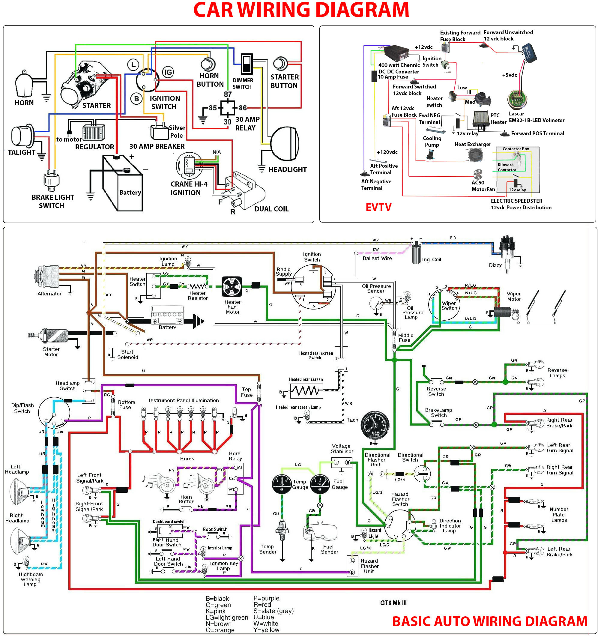
There’s no single “car wiring diagram” that applies to every vehicle – wiring layouts differ by make, model, and year. What’s universal is the symbol system used to draw them, and once you know it, you can read the specific diagram for any car.
The basic building blocks
- Lines represent wires. A small dot where two lines cross means they’re connected; a line crossing another with no dot means they simply pass over each other without connecting.
- Wire color and often a printed code (like “BK/WH” for black with a white stripe) identify a specific wire physically in the harness – useful for matching what’s on the diagram to what’s actually in the car.
- The ground symbol – usually a set of horizontal lines narrowing to a point, or a downward-pointing triangle – marks where a circuit returns to the chassis, which serves as the negative return path back to the battery on virtually every car.
- Relays appear as a coil symbol (the low-current control side) paired with a separate switch symbol (the high-current load side) – a small signal switches a much larger current on or off.
- The ECU/PCM (engine or powertrain control module) is typically drawn as a labeled box with numbered pins, since it’s the central point most sensor and actuator circuits route through on a modern car.
How to trace a circuit
Start at the power source – almost always the battery positive terminal or the alternator – and follow the line through any fuses, switches, or relays in its path to the component (the “load”) it powers, then continue to where that circuit grounds out. Manufacturer diagrams include a legend at the start of the electrical section explaining that specific diagram’s symbol conventions, since minor variations exist between manufacturers.
Two safety notes worth taking seriously
High-voltage lines – on hybrid/EV drive circuits, typically marked in orange – carry lethal current and require insulated tools and proper training, not a standard multimeter probe. Separately, airbag (SRS) circuits are usually marked in yellow specifically as a warning: probing them with a test light or the wrong kind of meter can accidentally trigger deployment. Use a high-impedance digital multimeter on computer-controlled circuits generally – an old-style test light can draw enough current to damage a modern ECU.