
Electric Fuel Pumps
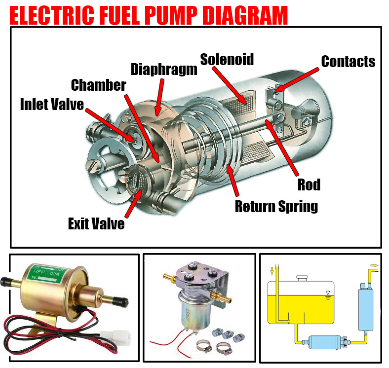
An electric fuel pump features a similar diaphragm-and-valve mechanism as its mechanical counterparts, but it uses a solenoid—a type of electromagnetic switch—to move the diaphragm instead of the camshaft.
Operation of the Solenoid Mechanism
The solenoid functions by attracting an iron rod that draws the diaphragm downwards, thereby creating a vacuum that sucks petrol into the chamber. Once the iron rod reaches the end of its travel, it forces a set of contacts to part, interrupting the current to the electromagnet. This interruption relaxes the pull on the diaphragm, allowing it to be raised by the diaphragm return spring. As the diaphragm ascends, it pulls the rod away from the contacts, causing them to close once more. This closing re-energizes the solenoid, which then pulls the rod and diaphragm back down. This cyclical action ensures a continuous flow of fuel.
Continuous Fuel Circulation
Unlike some systems that pump fuel only as needed by the carburetor, an alternative setup includes a complete loop of pipes running from the tank to the carburetor and back. In this configuration, the pump continuously circulates petrol, allowing the carburetor to draw the necessary amount of fuel from the ongoing stream.

Fuel and Air Filtration
Both petrol and air are filtered before entering the carburetor to maintain the system’s integrity. The petrol filter, often a replaceable paper element housed within a plastic casing along the fuel line, removes impurities. Some pumps also incorporate a wire or plastic gauze filter, and may feature a sediment bowl to trap debris. The air cleaner, typically a box over the carburetor’s air intake, contains a replaceable paper filter to ensure only clean air mixes with the fuel.